As a Coffee lover… of course this post had to start that way.
I have a dumb coffee machine for my morning coffee on my way to work. It is just an on-off coffee machine, the brewing cycle last around 10 min and then it just keeps warm the jar. Wouldn't it be a good idea to make it smart so the coffee will be ready when I wake up?
You can google "smart dumb coffee machine" and find some cool hacks. Some of them involves coffee machines that already have some programable functions, so they involve cutting some wires and solder them into an ESP8266/ESP32 module in order to use them.
In this case, I wanted to be the less intrusive with the coffee machine, meaning that in case of failure I will be able to detach and replace quick and easy. This makes the process more modular, just plug and play.
I thought about a few key points to make it work:
- The coffee machine on-off switch must be always on. One relay will control the on-off state of the coffee machine. This can be achieved by a single smart plug. However, the coffee machine will be on even if there is not water in the tank, this could lead to premature damage.
- In order to solve this, a water level sensor is needed to check if there is water in the tank. As it is needed to work the less intrusive possible, I decided to go with the XKC-Y25-NPN, which is a capacitive sensor so it can be placed outside the water tank.
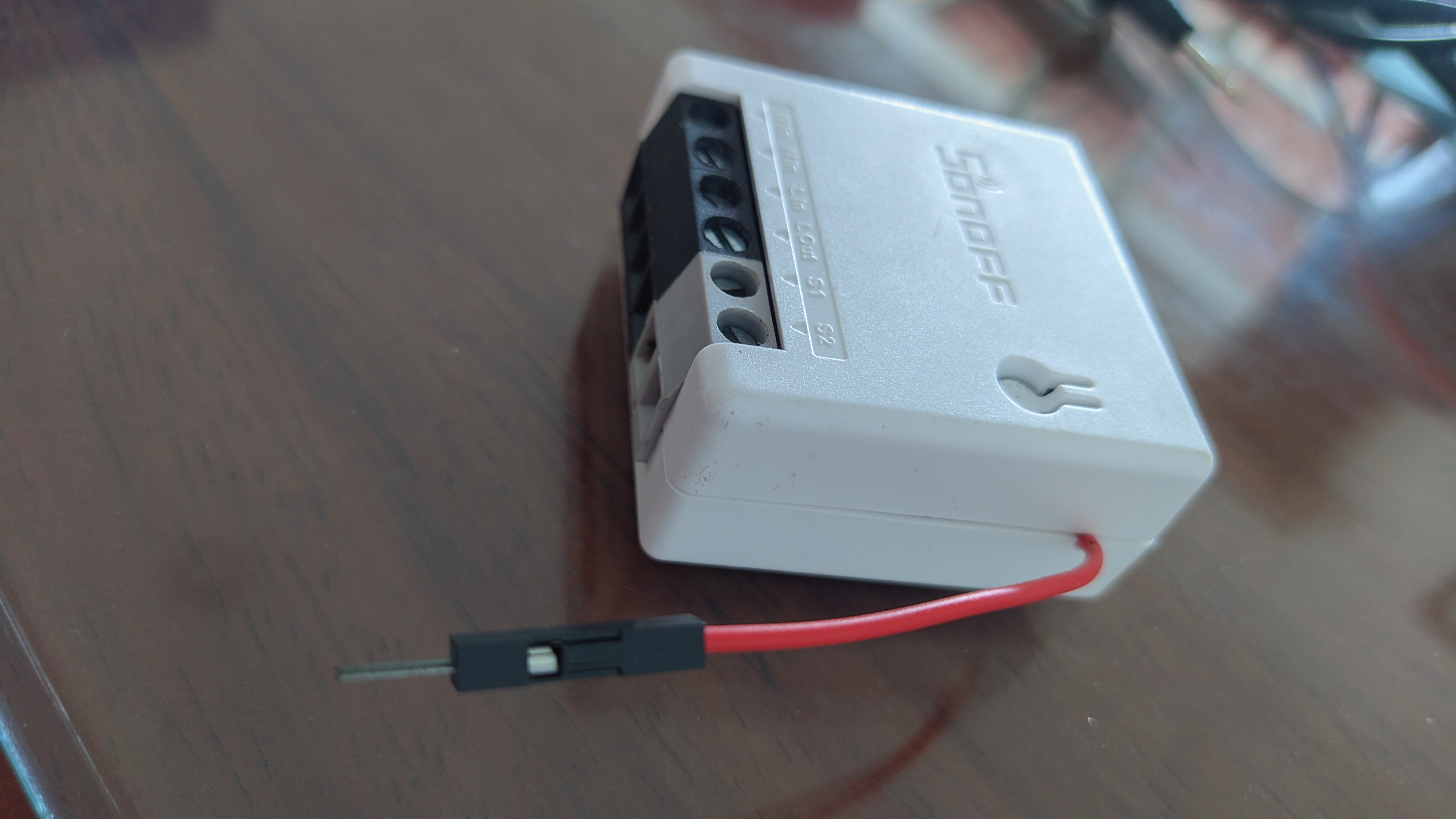
Finally, I decided to use a Sonoff mini R2, it provides a relay, 5V supply and it exposes the GPIO04 and ground trough the switch (S2 and S1 connections, respectively) that can be used to receive the signal of the water level sensor. So minor modifications are needed.
5V output from MiniR2 to XKC-Y25-NPN
According to the schematics, you can take a 5V supply from the MiniR2, Hackaday modded it to add a second switch, and you can see in the image where you can take the 5V supply
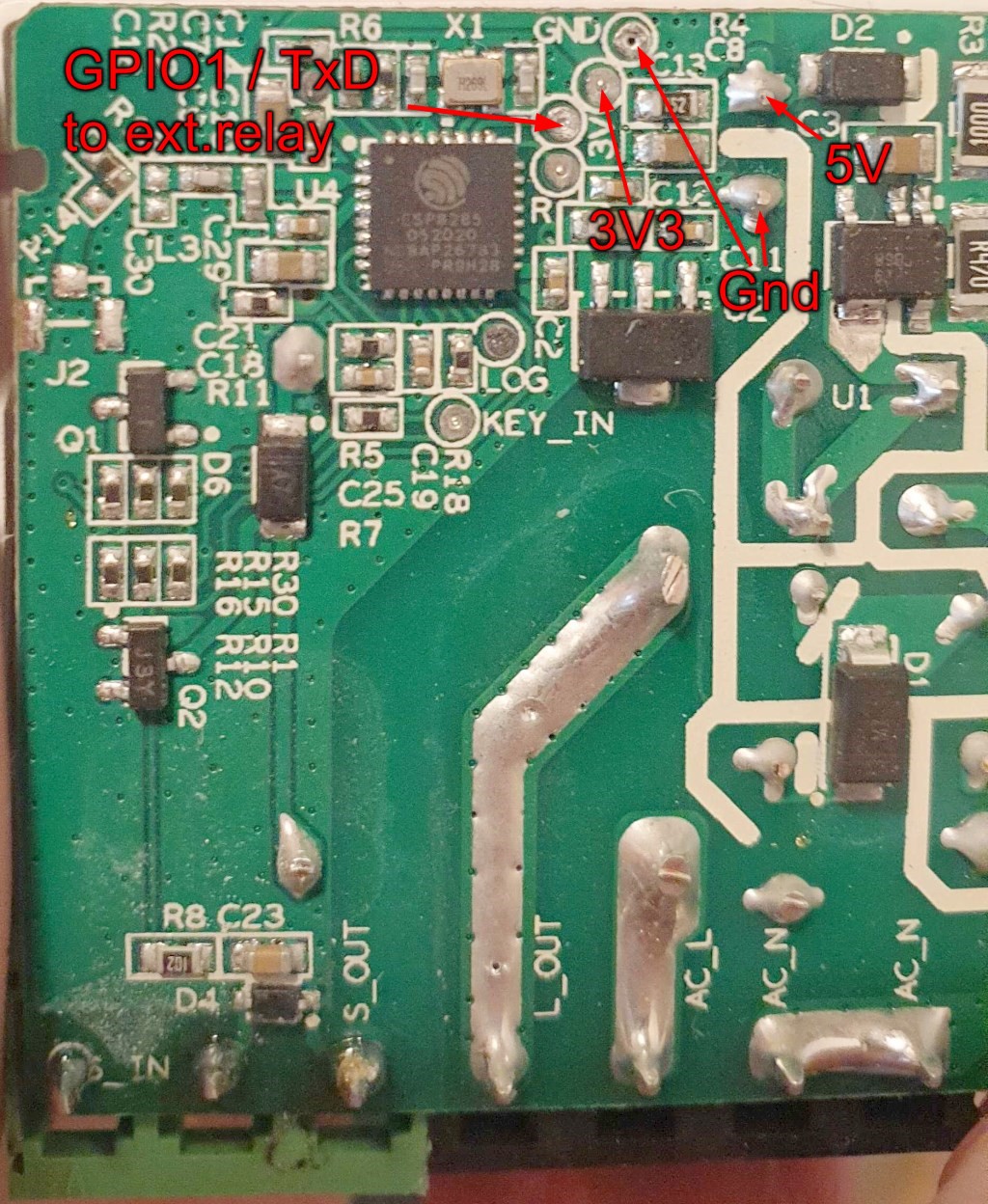
Solder a jumper wire where the 5V is located, it is thin enough to fit the little hole in the MiniR2 so the case will close completely without problem.
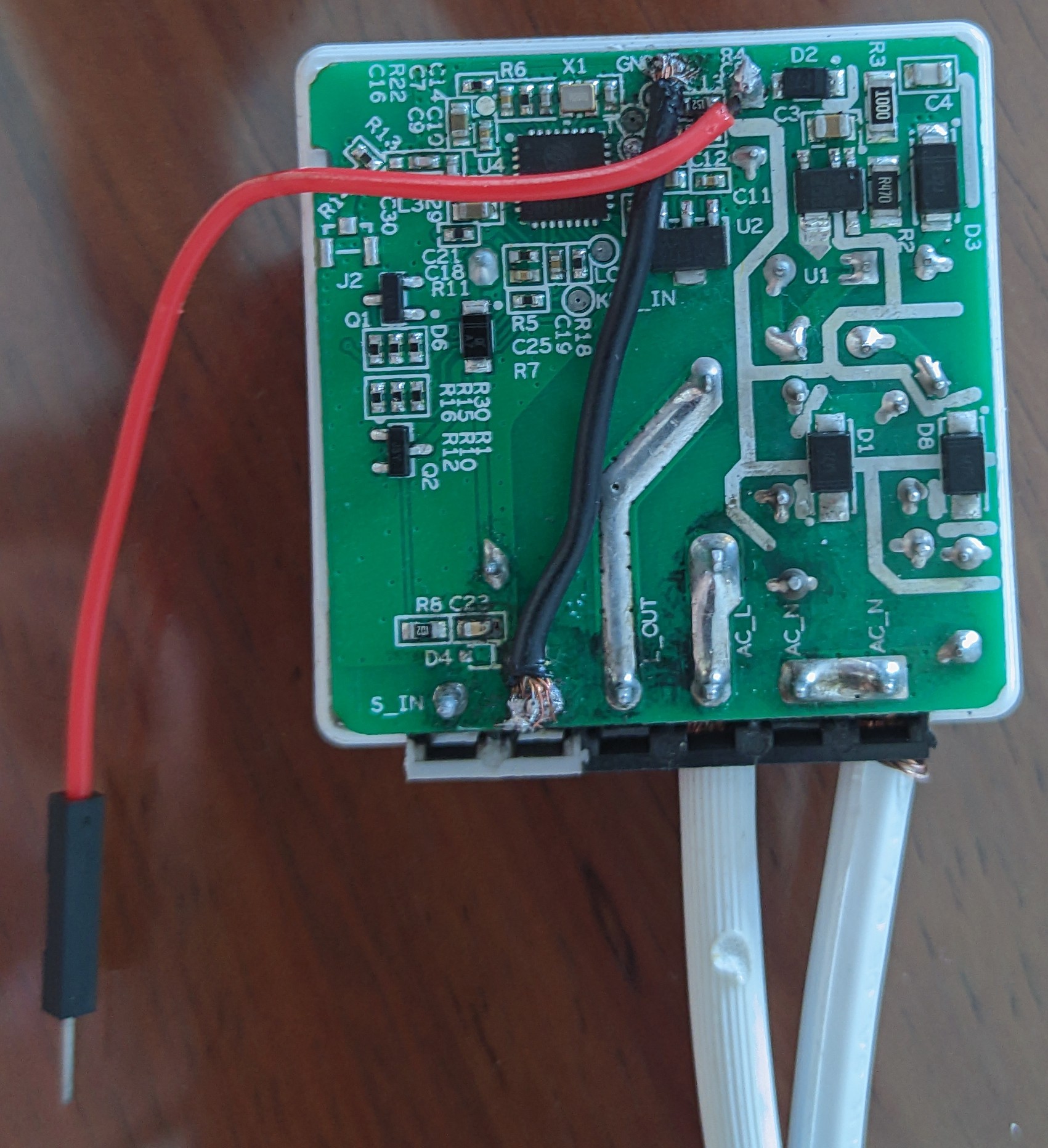 |  |
NOTE: ignore the black ground cable, I had to do this fix due to a previous mistake I made.
Connect the XKC-Y25-NPN
The XKC-Y25-NPN has 4 wires:
- Brown: 5V input (Vcc).
- Blue: Ground.
- Yellow: Signal.
- Black: Mode.
The black cable is not really needed, but it works this way:
Disconnected: Yellow wire will be connected to Brown (5V supply)
- This is the mode we want, as it works as a water detection sensor. If it detects water, it will send the signal, when connected to a led the led will turn on. Or when connected to a relay, it will close the relay turning on a water pump to avoid flooding.
If connected to Blue (ground), then Yellow wire will be connected to Blue (ground).
- This mode is useful to stop a water pump connected trough a relay, when the water reaches certain level. If water is below the desired level the relay will be closed (turning the water pump on), and when the water reaches the desired level it will open the relay (turning the water pump off)
Here is a helpful video to understand how it works.
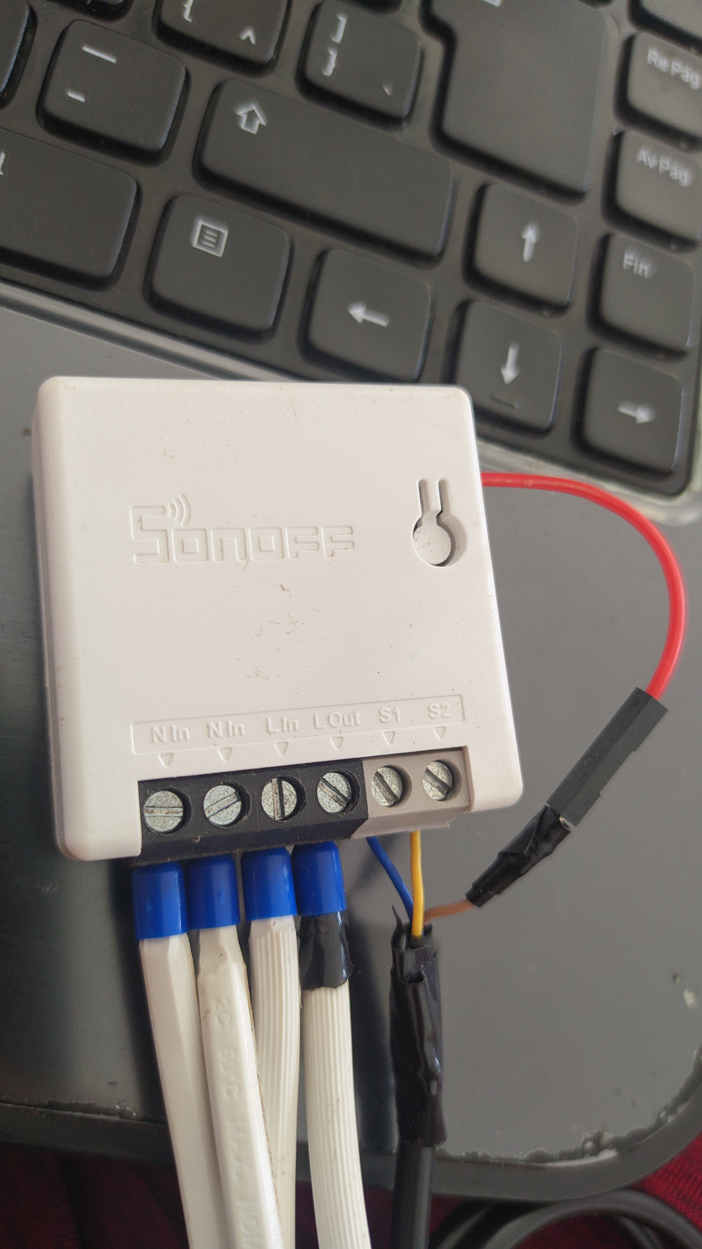
Connect the wires accordingly:
- Brown to 5V.
- Yellow to GPIO04 (S2).
- Blue to ground (S1).
ESPHome Code
For this part I am assuming you already know how to flash ESPHome in a the MiniR2. If not, take your time to google a little bit.
The yaml file includes by default: board, logger, api, ota, webserver, captive portal, etc. But the important part is the GPIO configuration.
For the MiniR2 we know:
- GPIO13, is the status led.
- GPIO12, is the relay.
- GPIO04, is the switch (S2)
- GPIO00, is the physical button.
- And Ground, is in the switch (S1).
So we create the entries for the status led and relay:
| |
Then we add a switch. Usually this would be controlled by the GPIO04 (S2) to toggle the relay, but we will use the GPIO04 for the water sensor. So this switch will not be linked to any GPIO but will turn on-off the relay when pressed from the webUI or homeassistant.
| |
Then we define the physical button use. On press it will toggle the switch that eventually will turn on or off the relay.
| |
And finally, under the same binary_sensor declaration we place the water sensor. We add the device_class as moisture so it will show "Dry" or "Wet" when water is detected. After testing, I had to add the inverted: true in order to display correctly the wet/dry state.
| |
You can find the full yaml file here.
Result and automation
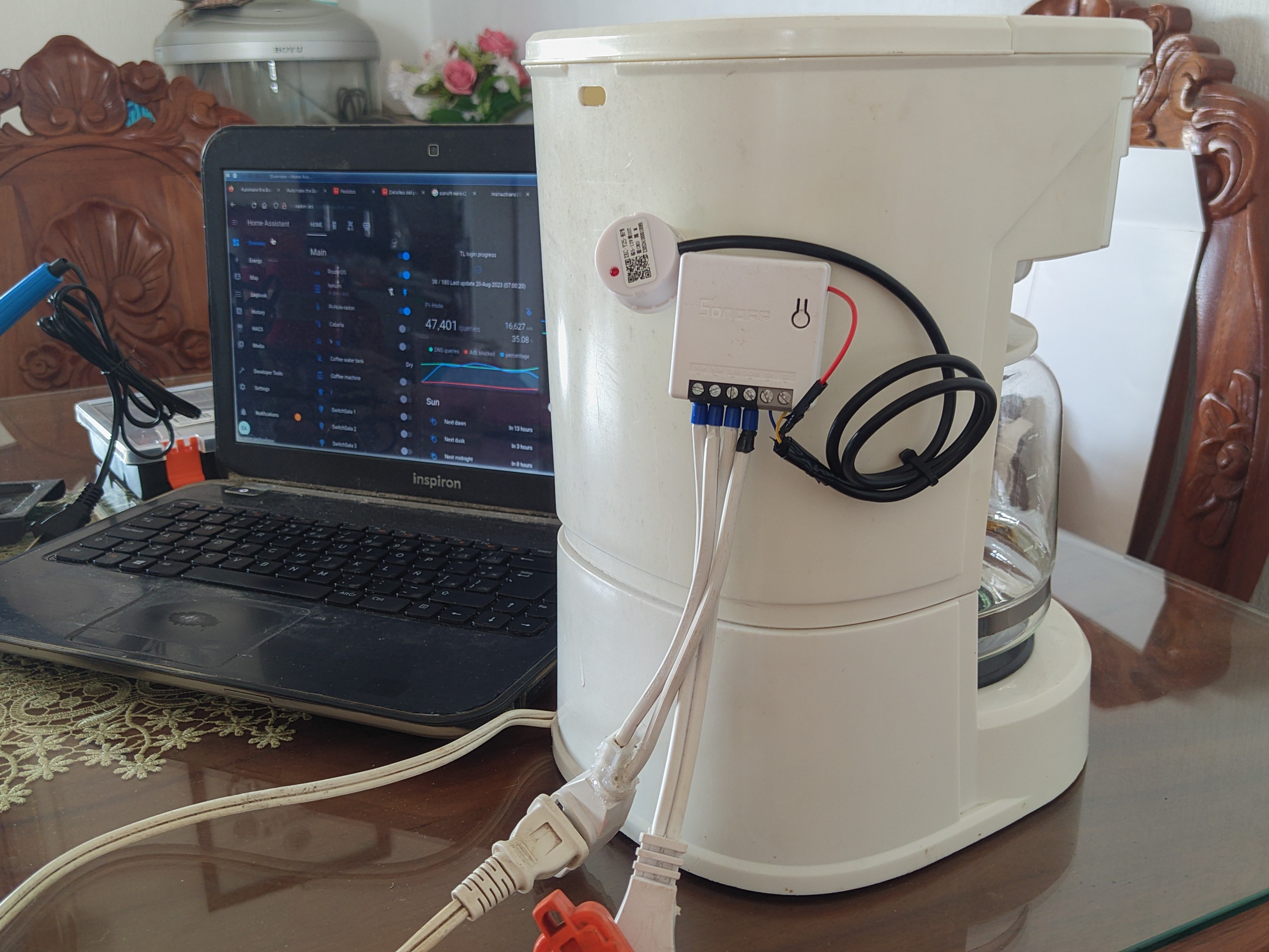
That's it, plug the coffee machine to the MiniR2 (I am using an extension cord) and place the sensor in the desired level. They can be placed with double sided tape, or anything else. Remember it is plug&play.
Once connected, add the device in homeassistant and you should see the switch state and water level sensor.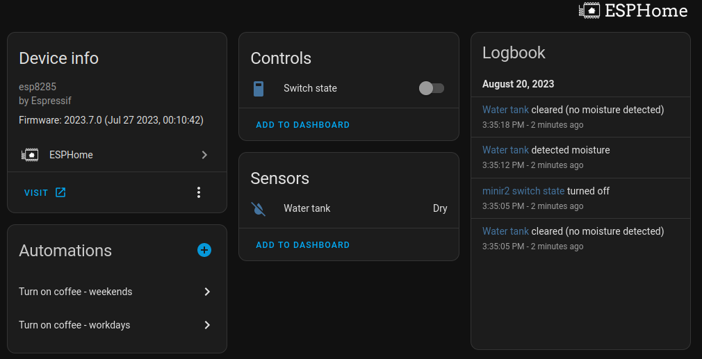
Finally, create an automation that follows the next logic:
- From Mon-Fri at 7am
- If water tank = Wet
- Then turn on relay
- Sleep for 30 min
- Then turn off relay.
It should look like this in yaml syntax, but I created it using the homeassistant visual editor which is easier to use:
| |
Final thoughts
- Well it works and it can be used with the generic Tuya smart switches, you just need to find out where to take the 5V output and configure it using esphome-libretiny.
- You can add the automation directly to the ESPHome yaml so the device flashed with compiled firmware will work independently from homeassistant. So even if your homeassistant is down, you will still have coffee. To do so, please follow the ESPHome automation guide.
- I actually have like 4 esp32 that I haven't used. One of them was planned for this purpose, together with a relay and a hlk-pm01, but the MiniR2 provides the relay and power supply in a small form factor, so that was the reason I ended up doing this.
- Since it worked nicely, now I am planning to use the MiniR2 together with PZEM-04T for energy monitoring. It needs more modding, since the PZEM-04T requires 2 pins for communication Rx/Tx, but I think it is feasible and it will be still small form factor.
- Enjoy your coffee!